Support
File Download
1.Download the specification PDF documents
2.Replaceable plate drawing files
Videos
Vacuum table video collection
PRE Vacuum Table Working On VMC
Fixing Thin Plates with Through Holes
PRI Vacuum Table Operation Tutorial
No Pressure Drop when Draining
Vacuum Table for Surface Grinder
Automatic Liquid Separation Demon
Difference of PRI&PREO&PRE Version
Device Connection Demon
PRO&PRE Cleaning Demo
Modular Vacuum Clamping Table Demo
SOVAC Vacuum Table Setup Demo
3-Phase Vacuum Pump Setup
Vacuum Table Usage Guide
1. Multi-hole Vacuum table Usage Guide
1. The Vacuum table is designed with multiple hole independent suction holes and does not require sealing ropes. Place the Vacuum table in the appropriate position on the worktable of the CNC machining center. The Vacuum table has clamping grooves on both sides, which are used to secure it to the worktable with clamp plates.
2. If high machining precision is not required and the workpiece does not need to be milled through, it can be directly placed on the soft surface for machining. For high precision requirements, the included replacement plate can be installed. After installing the replacement plate, its upper surface needs to be milled with face milling cutter to achieve a smoother and better finish. After multiple milling operations, the remaining thickness of the replacement plate is insufficient. You can download the electronic drawing(DWG format)of the replacement plate from the website (https://sovacuumclamp.com/support/) to manufacture a new replacement plate.
3. Connect the equipment according to the schematic diagram right, If the vacuum pump provides the air source for the system, there is no need to use a vacuum generator. and then test if the entire system can operate normally.
4. Place the workpiece on the surface of the vacuum chuck. Open the switches one by one based on the areas covered by the workpiece (there is only one switch for Professional Vacuum table and Premium Vacuum Chuck). No need to open switches for areas without a workpiece. The workpiece should be securely sucked in. Try to verify this by twisting the workpiece horizontally by hand. If a replacement plate is used and blanks of the same size are processed in batches, locating pins can be installed on the aluminum alloy replacement plate.
5. Start the CNC machining center and begin milling the workpiece.
6. After finishing the machining of the workpiece, use a dust blowing gun to clean debris and coolant from the surface of the vacuum chuck. Then, sequentially close the switches of the vacuum chuck. The workpiece can then be easily removed.
7. At the end of a day’s machining operation, it is necessary to clean the interior of the vacuum chuck. Set the switches of the Vacuum table to half-open position and pour some clean water onto the surface. The water will be quickly sucked into the interior of the vacuum chuck,The fast water flow is conducive to fully cleaning the remaining powder chips and cutting fluid inside. and discharged by the coolant separator. For Primary Vacuum table with segmented vacuum areas, each switch needs to be partially opened for cleaning individual areas.
8. If the workpiece is graphite or fiberglass (not recommended for Professional Vacuum table and Premium Vacuum Chuck), after machining each workpiece, connect positive pressure to blow back the vacuum chuck. Slowly open the positive pressure switch during blowback. Other material workpieces do not require blowback with positive pressure; completing the cleaning in step 7 at the end of the day is sufficient.
9. If the Vacuum table will not be used in the short term, ensure to clean the interior thoroughly, air dry it, and then store it back in the packaging box. For long-term storage, the surface of the vacuum chuck, including the suction holes, should be covered with protective film. It is strictly prohibited to leave the Vacuum table unprotected and exposed to the workshop environment for an extended period, as workshop dust can accumulate in the suction holes’ screen, affecting suction efficiency.
10. When separating the aluminum alloy replacement plate, you need to use the provided 0.18mm diameter molybdenum wire to pass between the replacement plate and the soft surface, otherwise the replacement plate will be difficult to remove. The molybdenum wire helps to separate the aluminum alloy replacement plate.
2. Automatic Vacuum Coolant Separator Usage Guide
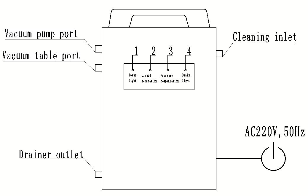
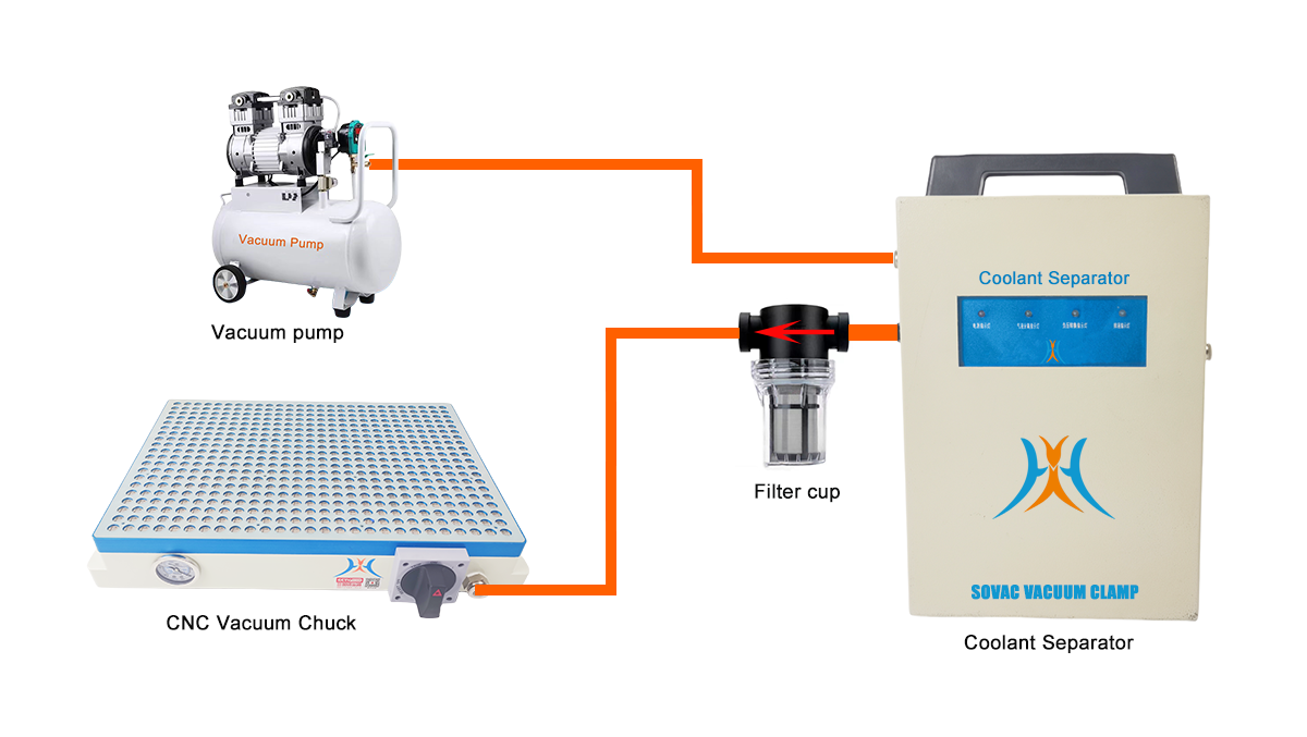
1. First, connect the vacuum chuck inlet of the coolant separator to the filter cup, ensuring the arrow on the filter cup points towards the coolant separator. Connect the other end (opposite the arrow) to the vacuum chuck. Connect the vacuum pump inlet to the vacuum pump or vacuum generator. Ensure the coolant separator is vertically positioned or hung securely on a hook to ensure proper operation. Blocking the cleaning inlet is strictly prohibited as it will prevent proper drainage.
2. Power on the device. The No. 1 indicator light will constant light (red). The operational power supply is AC 220V, 50Hz, single-phase. If this requirement is not met, purchase a transformer to convert the voltage.
3. Once a sufficient volume of coolant has accumulated in the coolant separator, lights No. 2 (yellow), No. 3 (yellow), and No. 4 (green) will light up nearly simultaneously. The drainage outlet switch will automatically open to discharge the collected coolant. After drainage completion, lights No. 2, No. 3, and No. 4 will light off. The drainage cycle depends on the rate at which coolant collects inside the vacuum chuck. The drainage threshold is factory-set and requires no further adjustment.
4. Regularly check the filter cup for accumulated debris and promptly clean it.
5. During operation, if lights No. 2 and No. 3 are not light up simultaneously, remove the filter plug from the cleaning inlet and replace it with an air tube connector. Use a 12mm air tube to connect positive pressure to the cleaning inlet and clean the interior of the coolant separator. Applying positive pressure to the cleaning inlet will not affect the normal operation of the coolant separator. The coolant separator will continue to function while being cleaned until lights No. 2 and No. 3 resume light up, which typically takes less than 2 hours. After cleaning, remove the air tube and air tube connector, and reinstall the filter plug into the cleaning inlet. Normally, cleaning is required once every two years.
6. Under normal operating conditions, The cleaning inlet does not need to be connected to positive pressure, and the cleaning inlet is strictly prohibited from being blocked. This model of coolant separator is suitable for both seal cord vacuum chucks and porous vacuum chucks.
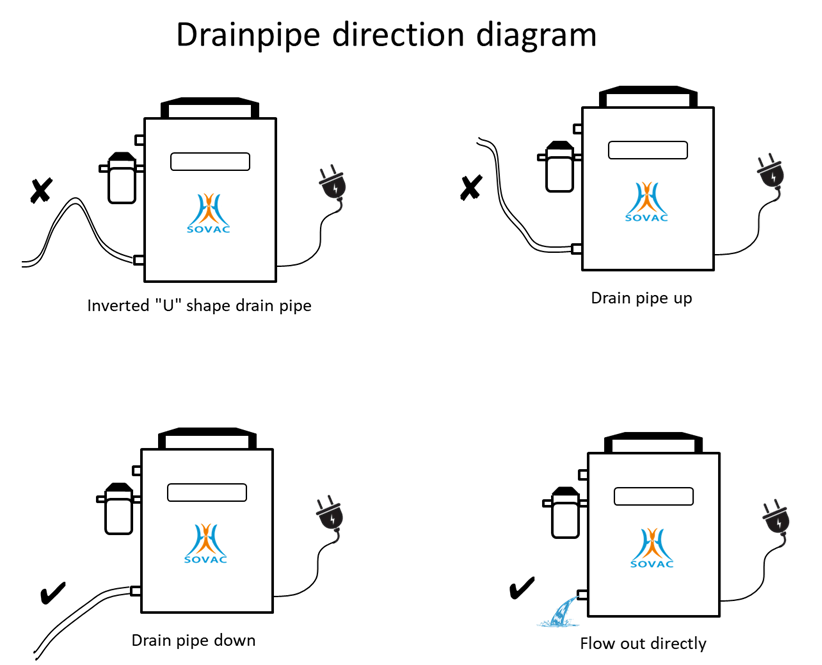
7. Generally, it is not necessary to install a drain hose. Direct the drain port to the sink and the cutting fluid can be directly drained into the sink. If you need to install a drain hose, please install the drain hose according to the connection scheme shown in the figure below.
FAQs
Technical
1. What materials can be sucked?
There are no special requirements for the material, mainly for the flatness and parallelism, iron, non-ferrous, non-metallic, polymer materials can be sucked.
2. What is the minimum size area of a single workpiece?
The minimum workpiece area of the professional vacuum table is recommended to be not less than 9cm*9cm, and the minimum workpiece area of the premium vacuum table is not less than 8cm*8cm.
3. What are the requirements for the flatness and parallelism of the workpiece?
The flatness should not exceed 3.2 μm, and the parallelism should not exceed 0.2 mm.
4. Is an automatic liquid separator necessary?
Since a small amount of cutting fluid and microscopic chips enter the vacuum table during machining,Cutting fluid must be prevented from entering the vacuum pump via an automatic liquid separator.
5. Can the air compressor provide air source for the vacuum table?
Yes, but you need to install a vacuum generator to convert the positive pressure of the air compressor into negative pressure.
6. Can vacuum table be applied on surface grinding machines?
We have a special surface grinding machine vacuum table, the specific size needs to contact the manufacturer for customization. Can be customized into rectangular and round shapes.
7. During the machining process, is it allowed to mill through the workpiece?
The workpiece can be milled through at one time, and the suction hole at the milling position will be automatically closed, which will not affect the normal work of other suction holes.
Orders
1. How long is the lead time?
For some specifications and models, if not in stock, the production cycle is generally 30 days, and you also need to consider the time of international shipping.
2. I am a distributor of CNC tools, can I contact you and act as an agent for your products?
We welcome companies that are engaged in the distribution of CNC accessories worldwide